
What Is a One Phase Transformer and How Does It Work?

A One Phase Transformer is a practical electrical device that transfers energy between circuits through electromagnetic induction. It usually contains two insulated windings around a laminated iron core. The primary winding receives alternating current, while the secondary winding delivers a changed voltage. No direct electrical connection is required between them.

This arrangement supports safer and more flexible power distribution. A transformer may reduce household voltage for control equipment or increase voltage for specialized applications. The turns ratio determines the approximate voltage change. For example, a winding with twice as many turns can produce roughly twice the voltage, assuming ideal conditions. Real transformers are less perfect. Core losses, winding resistance, heat, and sound reduce efficiency.

In a workshop, you might notice a low hum from the core and warmth near the enclosure. These details can reveal normal operation, but they should not replace proper testing. Qualified technicians inspect insulation, grounding, load capacity, and temperature before continued use. Manufacturer data remains essential because similar-looking transformers can have very different ratings.

The working principle seems simple. Its practical behavior is not always simple. Load changes can cause voltage drops, and poor ventilation can shorten service life. Understanding these limits helps engineers select, install, and maintain a One Phase Transformer responsibly. This guide explains its construction, operation, common uses, advantages, and limitations. It also considers why correct sizing matters more than appearance. A compact unit may still handle serious electrical energy. Careful attention matters.
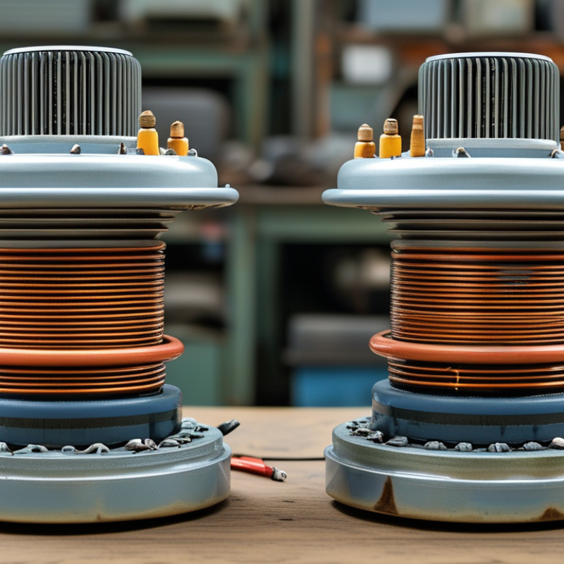
What Is a One Phase Transformer and How Does It Work?

Definition and Basic Purpose of a One-Phase Transformer

A one-phase transformer is an electrical device that transfers alternating-current energy between two circuits. Its basic purpose is to change voltage safely and efficiently. It may raise voltage, lower voltage, or provide electrical isolation.

The device uses two insulated windings around a magnetic core. The input winding, called the primary, receives alternating current. This current creates a changing magnetic field in the core. The field induces voltage in the output winding, called the secondary. More turns on the secondary usually produce higher voltage. Fewer turns usually produce lower voltage. This relationship is known as the turns ratio.

In practical installations, one-phase transformers support lighting, control panels, household equipment, and small distribution systems. A step-down transformer can reduce a higher supply voltage for safer equipment operation. Isolation transformers separate the input and output circuits, which can improve protection during maintenance. Electrical isolation matters too.

Technicians still need to check ratings carefully. Loose terminals, excessive heat, moisture, and overloads can shorten service life. Small details matter. A transformer does not create electrical energy; it transfers it, with some loss as heat and sound. Real load conditions may also change the expected output voltage. A simple definition can hide these operating limits, so installation data and measured conditions should guide every application.

What Is a One Phase Transformer and How Does It Work? - Definition and Basic Purpose of a One-Phase Transformer

Data Dimension Typical Information Explanation
Definition Static AC electrical device A one-phase transformer transfers alternating-current electrical energy between circuits through electromagnetic induction without changing the frequency.
Number of AC phases One phase The transformer is designed for a single-phase alternating-voltage supply and load arrangement.
Primary winding Input winding The primary winding receives the AC input voltage and produces an alternating magnetic field in the core.
Secondary winding Output winding The secondary winding delivers an induced AC voltage to the connected load. It may be electrically isolated from the primary.
Magnetic core Laminated ferromagnetic core The core provides a low-reluctance path for magnetic flux. Laminations help reduce eddy-current losses.
Operating principle Mutual electromagnetic induction Alternating current in the primary creates changing magnetic flux, which induces an alternating voltage in the secondary.
Voltage relationship V2/V1 ≈ N2/N1 For an ideal transformer, the voltage ratio is approximately equal to the secondary-to-primary turns ratio.
Current relationship I2/I1 ≈ N1/N2 Ignoring losses, a reduction in voltage corresponds to an increase in available current, and vice versa.
Frequency Unchanged from input to output A transformer changes voltage and current levels, but it does not act as a frequency converter.
Common voltage function Step-up or step-down A step-down transformer has fewer secondary turns than primary turns, while a step-up transformer has more.
Electrical isolation Available in isolating designs Separate primary and secondary windings can provide galvanic isolation while transferring energy magnetically.
Power rating Specified in volt-amperes (VA) or kilovolt-amperes (kVA) The rating indicates the apparent power the transformer can supply under specified temperature, voltage, frequency, and cooling conditions.
Efficiency Less than 100% in practical units Copper winding losses, core losses, leakage flux, and heating cause the output power to be slightly lower than the input power.
Main losses Copper loss and core loss Copper loss is mainly I2R heating in the windings. Core loss consists primarily of hysteresis and eddy-current losses.
Typical applications Residential, commercial, and light industrial systems Common uses include control circuits, chargers, lighting systems, electronic equipment, distribution supplies, and isolation applications.
Key limitation Not intended to convert DC directly Direct current does not provide continuously changing magnetic flux, so a conventional transformer cannot operate normally from a steady DC source.

Core Components and Their Functions

What Is a One Phase Transformer and How Does It Work?

Core Components and Their Functions

A one-phase transformer transfers alternating-current energy between circuits through electromagnetic induction. It changes voltage, not frequency. The core usually contains laminated electrical steel, which guides magnetic flux while limiting eddy-current losses. Two insulated windings surround this core. The primary winding receives input voltage, while the secondary winding delivers the changed voltage. More turns create higher voltage; fewer turns create lower voltage. Simple in theory.

In field inspections, the enclosure, insulation, terminals, and cooling path matter just as much. The enclosure protects live parts from dust and accidental contact. Insulation separates conductors and prevents short circuits between turns. Terminals connect the transformer to supply and load cables. Small units often rely on natural air cooling, while larger units may use oil and radiators to remove heat. A temperature rise of only a few degrees can reduce insulation life over time.

The U.S. Department of Energy’s 2024 distribution-transformer analysis estimates about 3.6 quadrillion British thermal units in energy savings over thirty years from improved efficiency standards. That figure highlights the importance of core quality and winding resistance, even when a transformer appears idle. IEC 60076 provides widely used requirements for transformer design, testing, and performance verification. Still, laboratory efficiency does not guarantee perfect field results. Loose connections, poor ventilation, and unbalanced loading can change actual performance. The textbook picture is useful, but incomplete.

What Is a One-Phase Transformer and How Does It Work?

A one-phase transformer transfers alternating-current energy between two windings through a magnetic core. The chart shows the ideal secondary voltage produced from a 120 V primary when the secondary-to-primary turns ratio changes.

Core components and their functions: The laminated magnetic core provides a low-reluctance path for alternating magnetic flux and helps reduce eddy-current losses. The primary winding receives the input voltage, while the secondary winding delivers the transformed voltage to the load. Insulation separates the windings and core, and the enclosure provides mechanical protection and electrical safety.

How Electromagnetic Induction Transfers Energy

What Is a One Phase Transformer and How Does It Work?

A single-phase transformer transfers electrical energy through electromagnetic induction. It uses two insulated windings around a shared magnetic core. The primary winding receives alternating current, which creates a changing magnetic field in the core. That changing field passes through the secondary winding. Faraday’s law then induces a voltage across its terminals. No direct wire connects the two circuits.

The voltage depends mainly on the turns ratio. If the secondary has more turns, the transformer can raise the voltage. Fewer turns can reduce it. The frequency must remain suitable for the core material and design. Direct current does not provide continuous flux change, so it cannot operate a normal transformer safely. The ideal model looks simple. Real units are less perfect.

During practical inspection, technicians may hear a soft hum or measure a slight voltage drop under load. Copper resistance causes heat, while core losses waste some energy through hysteresis and eddy currents. Laminated steel cores help limit those losses. Insulation also matters because damaged winding surfaces can create dangerous faults. A transformer may deliver its rated voltage without delivering its rated power. That difference is easy to overlook. Testing should include winding resistance, insulation condition, terminal tightness, and load behavior. A loose connection can become hot before the problem looks serious. A cooler enclosure is not proof of perfect performance.

Voltage Transformation and Key Operating Principles

A one-phase transformer transfers electrical energy between two circuits through magnetic induction. It uses a primary winding, a secondary winding, and a laminated iron core. Alternating current in the primary winding creates a changing magnetic flux. That flux passes through the core and induces voltage in the secondary winding.

The voltage change depends mainly on the turns ratio. If the secondary has more turns than the primary, the transformer increases voltage. If it has fewer turns, it reduces voltage. The relationship is expressed as Vs/Vp = Ns/Np. Frequency does not change during this process. In an ideal transformer, input power nearly equals output power, so higher voltage produces lower current. This trade-off is easy to overlook.

Real transformers are less perfect. Core losses, winding resistance, and leakage flux reduce efficiency. The output voltage may also fall when a heavy load is connected. A practical test uses a multimeter to compare no-load and loaded voltage, while keeping the circuit safely isolated and de-energized before inspection. The measured ratio will rarely match the calculation exactly. That difference is not automatically a fault. It may reflect heating, manufacturing tolerance, or the core design. Careful measurements matter. A quiet hum, warm winding, or unusual voltage drop deserves attention, because small operating changes can reveal problems before insulation damage occurs.

Common Types, Uses, and Safety Considerations

A one-phase transformer transfers AC energy between two circuits through magnetic induction. It changes voltage without changing frequency. A step-down unit can reduce distribution voltage for homes, control panels, and small workshops. A step-up unit serves compact generation systems and selected rural feeders. Isolation transformers separate circuits electrically, while autotransformers use one shared winding and usually need less material. That saving has a trade-off: isolation is weaker.

Use depends on load behavior. Residential service commonly uses single-phase distribution transformers because household loads are modest and uneven. Control transformers supply safer, lower voltages to relays, sensors, and industrial machinery. EIA reports that U.S. transmission and distribution losses have averaged about 5% in recent years. Correct transformer sizing can reduce avoidable heating, though it cannot eliminate grid losses. The U.S. Department of Energy also identifies transformer efficiency as a significant long-term energy-saving opportunity. Field measurements matter more than catalogue optimism.

Tips: De-energize, lock out, and verify absence of voltage before opening a cabinet. Follow OSHA procedures and NFPA 70E practices. Install overcurrent protection, proper grounding, and ventilation. Keep oil-filled units away from ignition sources and inspect for leaks. Watch humming, hot insulation, discoloration, or repeated breaker trips. These signs are not harmless. IEC 60076 provides core transformer testing requirements, but local codes still control installation. A mistake I still see is choosing capacity from normal load only; inrush current and future expansion deserve attention.

Go to Top